5 Steps to Prevent Messy Cables in Office Workstations
Trouble with messy cable management? In this article, you will master how to route cables from user devices to building connections and furniture.
Start power and data coordination before finalizing an office workstation layout. The project team needs to understand what users will connect, where building outlets and data points are located, and how cables will reach each workstation without interfering with circulation or furniture access.
This checklist follows the path from user devices to building connections and furniture cable routes. It also identifies what to confirm before releasing drawings and furniture specifications.
Start with Devices, Users and Expansion Assumptions
Begin with the equipment used at each workstation. A standard desk setup may differ from a position with multiple displays, a dock, a phone, shared peripherals or other project-specific equipment. Record the devices by workstation type or team so the layout and service plan reflect actual use.
Confirm the number of users and workstations, which positions operate simultaneously, where shared equipment will be located, and whether additional devices or workstations are expected later. Treat future expansion as an assumption to verify against the available space and project scope, not as a guaranteed capacity.
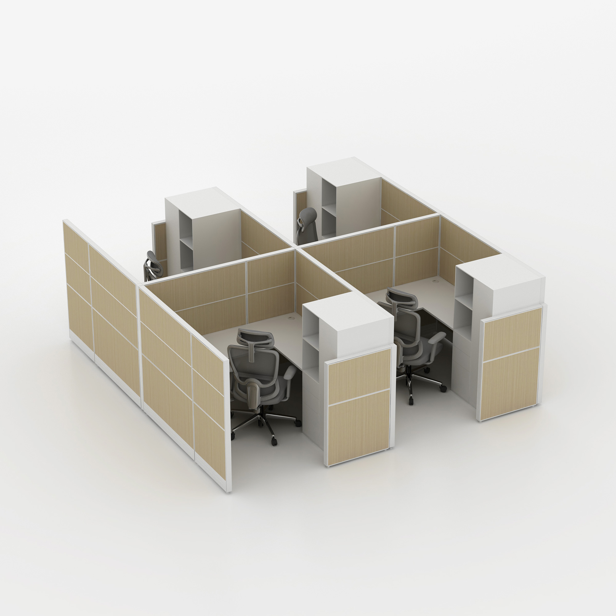
At this stage, the useful output is a coordinated device list and workstation count that the designer, contractor and furniture supplier can review together. Furniture options such as cubicle workstations can then be assessed against the project’s cable-routing requirements. The selected configuration and service connections still need project-specific confirmation.
Map Building Feeds, Floor Boxes and Wall Points
Begin with the latest electrical and data drawings. The project team should mark power feeds, floor boxes, wall outlets and workstation groups on the same plan. This makes it easier to see which service points are intended for each group, where cables can enter the furniture, and whether a proposed route crosses an aisle or shared access area. Mark existing points separately from proposed or unverified locations so the drawing shows which information still needs coordination.
The electrical and data contractor should verify service-point locations against site conditions and confirm the supply requirements for the listed devices. This check belongs with the relevant building-services team because the furniture layout alone cannot establish the available supply.
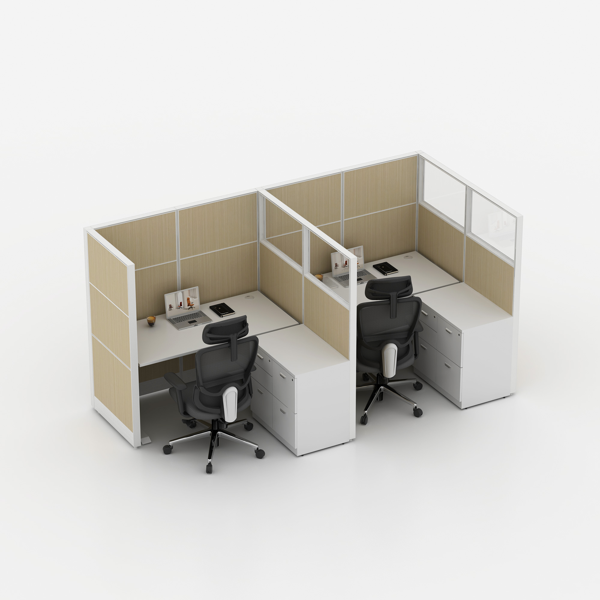
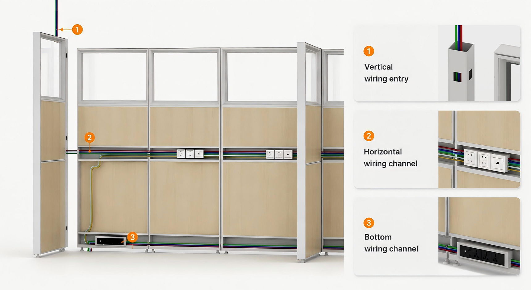
The furniture manufacturer should confirm where cables enter the selected workstation and how they connect with the planned service points. EGROspace’s cubicle workstation range lists the E60 system with concealed cable routes inside the screens. The designer can then update the coordinated layout to show the agreed workstation positions and connection routes.
 |
 |
Choose Furniture Entry Points and Cable Routes
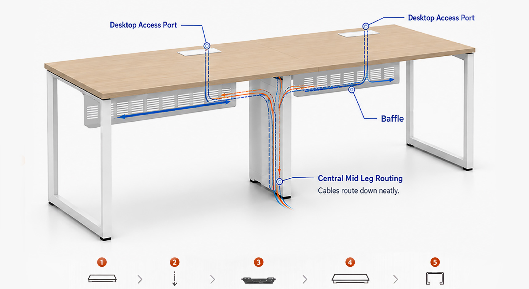
After the service points are mapped, show how cables will travel from each point to the workstations. On the furniture plan, identify the entry point into the desk or support frame, the route beneath the work surface and the exit point for user devices. For connected benching rows, show how the route continues between workstations and where each desk receives its connection.
Check that the proposed route aligns with the selected desk configuration and keeps connections accessible for installation and maintenance. Mark floor boxes, cable entry points and desktop access points on the same drawing. This helps the project team catch mismatches between building services and the furniture layout before the workstation plan is released.
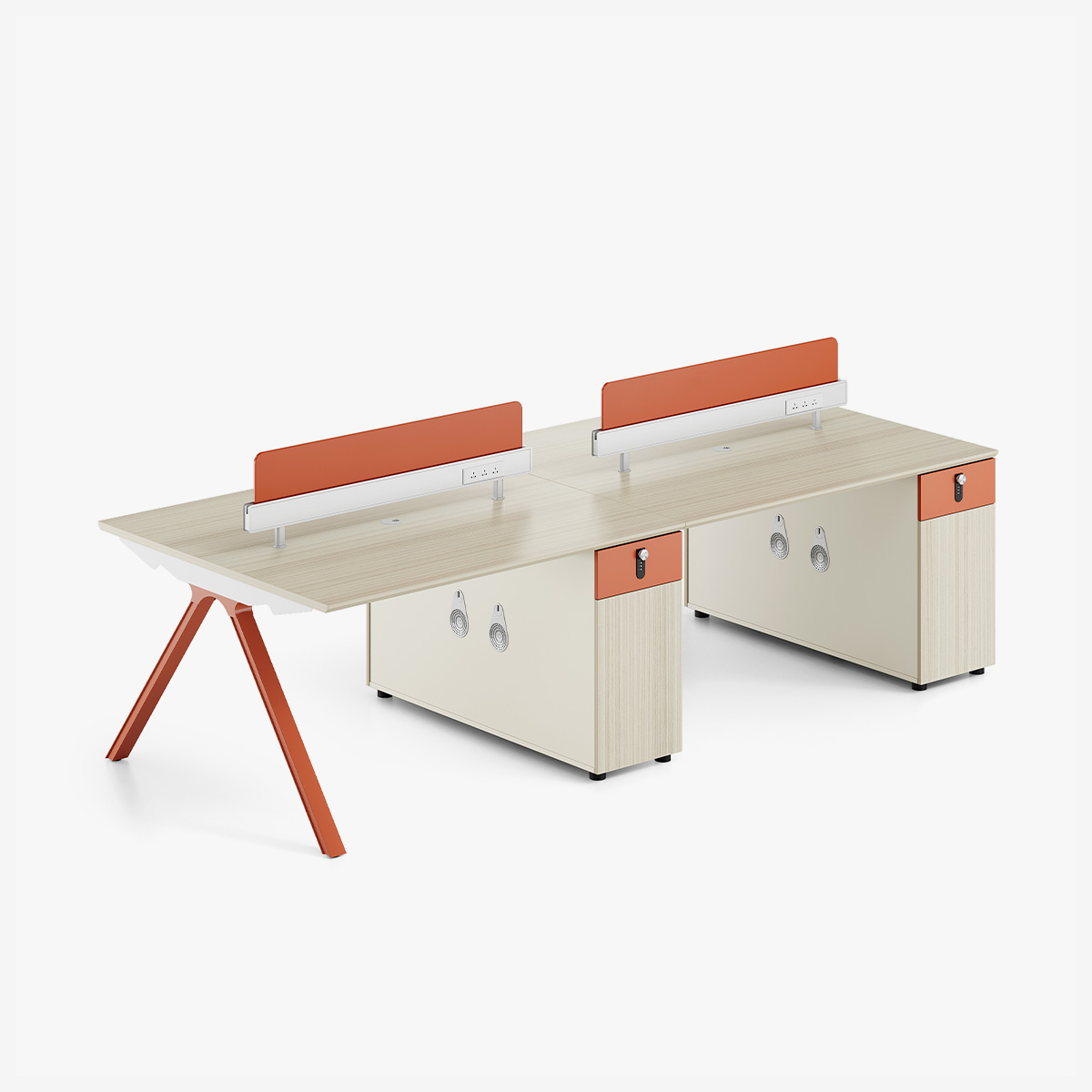
EGROspace’s Forma Benching Workstation has desktop cable access and a vertical cable path through its central support, connecting floor services with desktop connections. Use its product drawing to coordinate those entry and exit points with the project’s service layout.
 |
 |
Coordinate Power Modules, Data, AV and Cable Separation
For each workstation type, confirm which connections users need: power outlets, data ports, monitor or docking connections, and any audio-visual equipment. Place the power module and data access where they're reachable from a seated position, then show their locations on the furniture plan. For shared work areas, check that the module layout matches the number and arrangement of desks.
The coordinated drawing should show the intended power and data routes, including where they run together or separately. The electrical and data teams can confirm any separation requirements against the project specification and applicable local requirements. This keeps the furniture route aligned with the building-services design without assuming a universal cable-separation rule.
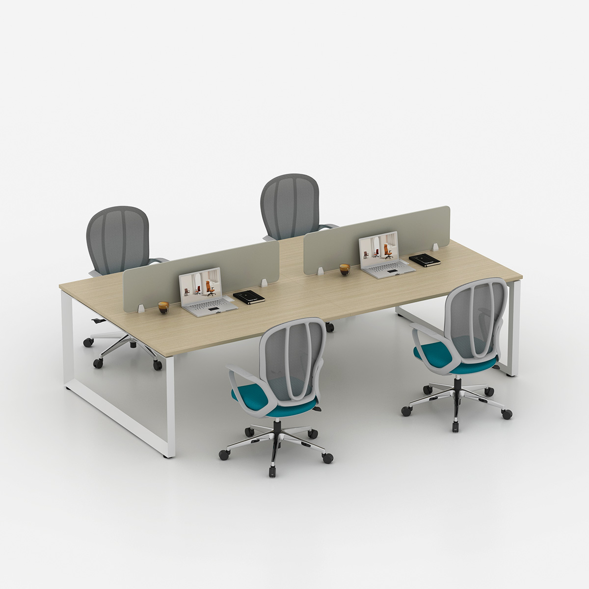
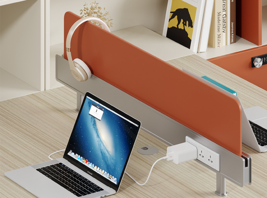
EGROspace’s Sanqin Workstation Desk has a built-in power module in the desktop screen, keeping charging access close to the user. This is a distinct example of module placement compared with the under-desk cable routing discussed in the previous section.
Preserve Access for Installation, Testing and Maintenance
The coordinated drawing should show the complete connection path: the building service point, furniture entry, cable channel and power or data module. Label each workstation group and indicate which panels, covers, or access points must remain reachable during installation. This gives the installation team a clear route to follow and helps avoid placing a connection behind a fixed furniture component.
The electrical and data contractor is responsible for checking the building-side points and connections. The furniture installer should confirm that the selected workstation’s cable channels and modules remain accessible once the desks and panels are assembled. Record the interface between the two scopes on the project drawing so both teams know where their work meets.
After installation, compare the connection locations with the approved layout and update the project record if the installed route differs. Keep the location of serviceable covers and modules in that record for future inspection or changes.
Power/Data Markup Checklist Before Furniture Release
Before releasing the furniture layout, the project team should compare the workstation plan with the device schedule and current electrical and data drawings. The markup should give the furniture, electrical and data teams the same view of where connections are needed and how they relate to each workstation.
- Identify each workstation or workstation group with a matching plan tag.
- Mark the relevant floor box, wall point or other building service location.
- Show the furniture cable-entry point, module location and route to the desktop.
- Identify required data or AV connections and note any project-specific cable-separation requirements.
- Assign each unresolved building-side or furniture-side interface to a responsible party.
- Record access points needed for installation, testing and future maintenance.
The designer should issue the markup with the same revision as the furniture plan. The electrical and data teams can then confirm their service requirements, while the furniture team confirms that the selected workstation accommodates the specified entry points and routing. Resolve open interfaces before the furniture package is released.
Conclusion
Workstation power and data planning connects user devices with building service points and furniture cable routes. Coordinating these elements on the same drawings helps the project team confirm connection locations, responsibilities and access before furniture release.
For a project discussion, prepare the latest floor plan, workstation and device list, electrical and data drawings, AV requirements and any expected expansion plans. Contact EGROspace to discuss the furniture requirements and project scope.